MOBILITY ASSIST DEVICE

Sharable Details
Due to confidentiality, we can not share all the details of the project
Introduction
The six-bar linkage follows the J-shaped trajectory of the shoulder joint and maintains orientation of the supporting bar for comfort and ergonomics. The overall goal was to design a biomechanically correct, comfortable, compact, lightweight, and portable under-actuated device. By following the natural posture and movement of the human body, a biomechanically correct STS motion is achieved.
Services: Mechanical design, prototyping, DFM, manufacturing support, test & verification
Tech Focus: Dynamics, FEA, CAD, and Prototyping
Deliverables: Parametric CAD, prototype units, test reports (high-level), full drawing set & assembly notes
Form Factor: Compact, lightweight, and ergonomic
Problem Statement
It is well-known that sit to stand is a biomechanically demanding task requiring muscle strength greater than other activities of daily life (ADL), such as ambulation or stair climbing.
over 6.8 million community resident Americans use assistive devices to help them with mobility,
Almost one-third of mobility device users need assistance from another person in one or more of the ADLs.
Existing STS devices are uncomfortable during STS transformation, since the user is not lifted through the natural posture and movement during the transformation.
Objective
A portable, self-use, compact, and multi-functional STS and ambulation assistance device is to be designed for elderly and disabled individuals to help them stand from a seated position and vice versa with minimal effort while stabilizing and arresting their fall during ambulation.

The device should provide sufficient body support to prevent the user from falling while standing, sitting, and walking, and follow the natural motion of lifting and lowering.

This device will be able to lift and stabilize a person with up to 300 lb.

The device should be able to lift an average individual whose height ranges from 5’ to 6' by a distance of at least 19 inches within 30 seconds.
Background
During an STS movement, there are multiple muscles acting together to coordinate the motion of the body. The exact process can be broken down into separate procedures that are followed by the body while changing positions.
Steps (What We Did)

1
We sought to design a mechanism that mimics the motion trajectories of specific points of the human body, where the lifting mechanism support link could potentially support the patient.

We pick the shoulder joint trajectory to design this mechanism due to the versatile options of supporting at this joint.
2

A particular cognate of the four bar linkage mechanism is selected that has appropriate link lengths, joint
types and the joint and ground positions, which helps the mechanism to be easily positioned on a frame.
3
design specifications require the mechanism to lift by a vertical height of 19 inches. To minimize the overall weight and the cost of the device, it is important to select an actuator that requires minimal extension while also providing adequate force. Appropriate mounting point was selected, which displaces the support bar vertically by 19 inches while the actuator extends by only 8 inches.


4
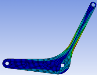
Simulation
-
Conduct FEA using:
-
HyperMesh for meshing.
-
Abaqus for stress analysis.
-
-
Simulate full motion cycle with actuator loads (6,000 N) and user weight distribution (150 lb per side).
-
Results:
-
Maximum von Mises stress ≈ 148 MPa at critical frame junctions.
-
Safely below Aluminum 6061 yield strength (~276 MPa).
-
5
Design optimization
-
Perform geometry optimization of links to minimize weight.
-
Evaluate joint reaction forces across cycle (via dynamic analysis).
-
Iterate design for:
-
Reduced deflection.
-
Balanced stress distribution.
-
Compact geometry (Figures 10–11 show before/after optimization).
-
6
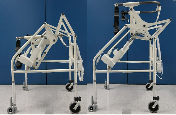
Prototyping
-
Fabricate using machined Aluminum 6061 members.
-
Integrate:
-
Two six-bar linkages.
-
Two LINAK actuators.
-
Harness for hip support.
-
Control electronics (manual or button-actuated lift/lower).
-
-
Assemble as a walker-like frame allowing both STS and ambulation functions.


Conclusion (Outcomes)
We presented a novel planar six-bar mechanism for executing natural trajectories and motions of human body during the sit-to-stand motion. The mechanism is integrated in a portable, compact, self-use walker-like device, which completely lifts users, supports them during ambulation, and arrests fall. A NY-state based physical therapy and rehabilitation company is bringing this device to the market. This assistive device and the underlying technology are at the cusp of creation of a successful product that could potentially enable millions of disabled people around the world to live with their loved ones independently and with dignity, or with more independence and safety in assisted living facilities or nursing homes. From a value proposition perspective, patients constrained to stay at such facilities still derive mobility independence and comfort benefits, but it is the other constituents, such as clinical rehabilitation directors, care givers, physical and occupational therapists, and the facility managers who also benefit by reduced risk management, workers' compensation liability, lower cost, and improved care and outcomes.